Pumping water with steam


Beam Engine, Western Springs Pumping Station [1964.1] Museum of Transport and Technology (MOTAT)
Western Springs Beam Engine: Pumping water with steam
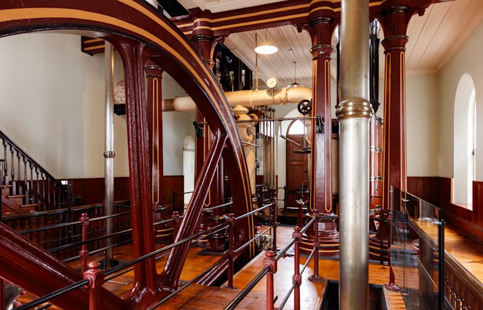
The beam engine housed in the Western Springs Pumping Station once pumped water from Te Wai Ōrea / Western Springs to supply fresh water to Tāmaki Makaurau / Auckland. In regular service from 1877 until the 1920s, the engine now sits as a focal point of MOTAT’s Great North Road site. It has been restored to an operational state and is run on special occasions.
What is a beam engine?
A beam engine is a type of engine where a beam, pivoting in the middle, rocks up and down like a seesaw driven by the engine’s pistons at one end, and driving an output at the other. Beam engines were the first practical type of steam engine and were instrumental in driving the industrial revolution.
The beam engine was invented by Thomas Newcomen in England in 1712. However, Newcomen’s engine was not a true steam engine as the steam produced was used to create a vacuum under the piston when condensed, causing it to be pushed down by atmospheric pressure acting on the piston from above. It is therefore known as an atmospheric engine. The return stroke was due to the pumping rod at the opposite end being weighted to pull the beam down. Chains connected the ends of the beam to the piston and pump as the engine only exerted downward forces. Newcomen engines spread throughout Britain during the 18th century and were extensively used for draining water from the many coal and metal ore mines.
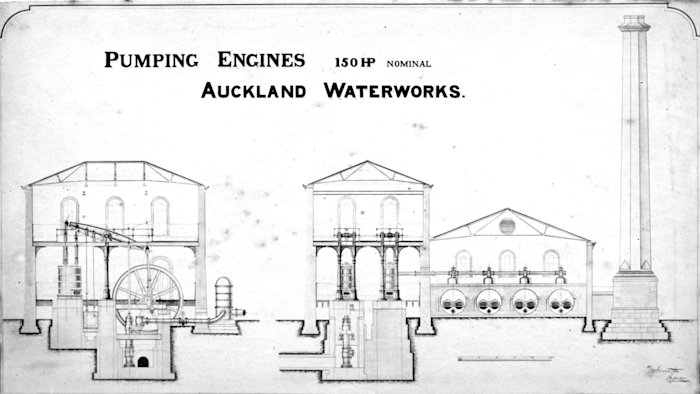
Illustration of a Newcomen atmospheric engine showing the boiler and piston cylinder on the left and pumping or winching apparatus on the right. Image from Figuier, L. (1868). Merveilles de la science. Furne Jouvet et Cie, Paris. In the public domain.
It wasn’t until the mid-18th century that the first true steam beam engine was created by James Watt. Watt took Newcomen’s design and made several improvements to it, making it significantly more efficient. The condensing phase was removed from the piston cylinder to a separate condenser. This allowed the cylinder to remain hot and the condenser cold meaning energy wasn’t wasted reheating the cylinder between cycles. Watt also sealed the top of the cylinder making it airtight. Pressurised steam pushed on the top of the piston working against the vacuum of condensed steam underneath, thus driving the piston down. This was the birth of the steam beam engine.
Further developments devised by Watt and his associates continued to improve the effectiveness of the steam beam engine during the late 1700s. Watt’s parallel motion linkage replaced the chain connections from the beam ends. A sophisticated mechanism consisting of a hinging parallelogram allowed a rigid connecting rod to move with the beam without putting undue friction on the side of the piston. This led the way for creating a rotative engine converting the up and down reciprocating motion of the beam to a rotational movement which could in turn be used to drive other machinery. Watt also patented the double-acting cylinder where a series of valves meant steam could power both strokes of the piston. Coupled with the rigid connecting rods, this meant the engine both pushed and pulled the beam through its movement.
Beam engines developed into a wide array of different types and configurations. They also come in a range of sizes from building sized behemoths such as the Western Springs beam engine, to small standalone engines such as the one at the Dunedin Gasworks Museum, the only other known historic beam engine remaining in New Zealand.
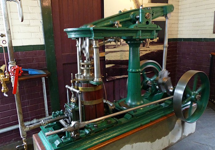
1868 Garrison Foundry beam engine at the Dunedin Gasworks Museum. Image supplied by Dunedin Gasworks Museum, all rights reserved
How does it work?
Expansion and contraction
The process starts in the boiler house where water is heated in the boiler turning it from a liquid to a gas (steam). The water molecules in steam move further apart due to their increased energy. However, in a boiler the steam is restricted to a limited volume. The pressure increases as the steam tries to expand but has nowhere to go.
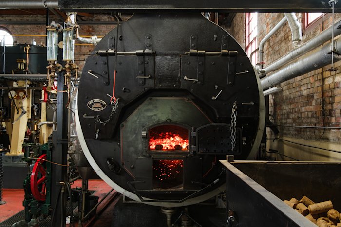
MOTAT’s operational Daniel Adamson & Co. boiler [2005.90] Museum of Transport and Technology (MOTAT)
When the pressurised steam from the boiler enters the piston cylinder of the engine, it expands to fill the space and pushes the piston upward, powering a stroke of the engine. The Western Springs beam engine has double-acting cylinders, meaning that steam enters the cylinders alternately on both sides of the piston and therefore powers both upward and downward strokes of the piston.
The Western Springs beam engine is a double-expansion compound engine. Compounding steam engines increase efficiency by expanding the steam multiple times, extracting more energy before it is exhausted. A double-expansion engine will expand the steam twice, once in a high-pressure cylinder and a second time in a low-pressure cylinder. The Western Springs beam engine is a specific type of compound engine known as a Woolf compound, named after its inventor Arthur Woolf.
Steam cylinders, Western Springs Beam Engine [1964.1] Museum of Transport and Technology (MOTAT)
After the steam has been expanded to the maximum the engine allows for, it is exhausted through a condenser. The condenser cools the steam by injecting a spray of cold water. This causes the steam to cool rapidly and condense back into water. As it condenses, the water molecules contract leaving an empty space or vacuum behind. This vacuum increases the efficiency of the engine by causing the steam to flow readily from high to low pressure. It is this difference in pressure across the system that powers the engine. The condensate water can then be recycled into the boiler and through the engine system again.
Energy transmission
The up and down motion of the pistons is transferred to the overhead beam via a set of connecting rods. The pistons move straight up and down, but the rocking motion of the beam means its ends move through an arc. This imbalance requires a sophisticated mechanism to reduce friction and undue wear on the pistons. Unlike earlier beam engines which typically use the Watt parallel motion linkage, the Western Springs beam engine uses a crosshead and guide bar mechanism.
Through this linkage the force of the pistons is transferred from one end of the beam to the other, moving the beam in a rocking, reciprocating motion. Two long connecting rods are attached to the far end of each of the beams. The outermost rod connects to a crank arm which turns the flywheel. The innermost rod drives the water pump below the engine.
Drawing of the Western Springs Beam Engine showing a section of the pump well beneath the floor [07-2440] Walsh Memorial Library, Museum of Transport and Technology (MOTAT)
Going steady
The Western Springs beam engine is a twin-cylinder or double engine. A pair of engines drive separate beams which are connected to a shared flywheel. The crank arms connect to the flywheel from the beams at 90-degree phasing. This provides an even turning moment, meaning the force applied spins the flywheel evenly. The two component engines are designated ‘A’ (western side) and ‘B’ (eastern side) and share the serial number 152. The A engine is no longer complete as parts of it (main pump, air pump, feed pump, and condenser) were scrapped during the Second World War.
Flywheel, Western Springs Beam Engine [1964.1] Museum of Transport and Technology (MOTAT)
The flywheel, 6 metres in diameter and constructed of 14.2 tonnes of cast iron, provides stability to the engine’s output. The spinning of the flywheel creates rotational inertia, a property that makes it more difficult to stop spinning. This is beneficial as it counteracts a drawback of the reciprocating motion of the pistons and beam. When the piston/beam is at its maximum downward or upward position its movement must stop before it returns in the opposite direction. The flywheel smooths out this transition by carrying energy over into the next cycle of the engine.
Governor, Western Springs Beam Engine [1964.1] Museum of Transport and Technology (MOTAT)
A centrifugal governor regulates the speed of the engine. It rotates relative to the engine’s speed. When the speed is low, the fly-balls sit near the axis of rotation. When the speed is high, centripetal force starts to overcome the downward gravitational pull and the balls move out and up away from the axis. The governor is connected to the steam intake and is calibrated so that if the engine is moving too fast less steam is provided thus slowing the engine. If the engine is moving too slow, more steam is provided to allow the engine to produce more force. In this way the governor regulates the operation of the engine keeping a smooth and steady output.
Camshaft and push rods, Western Springs Beam Engine [1964.1] Museum of Transport and Technology (MOTAT)
A series of push rods and rotating cams connect to the valve chest. The movement of the cams is precisely timed, opening and closing the sixteen valves in the correct sequence so that the steam flows through the engine as and when it should. This allows the engine to be self-acting.
History of the Western Springs beam engine
The Western Springs beam engine was built in 1876-77 as part of the Western Springs Pumping Station at the heart of Tāmaki Makaurau / Auckland’s first major public water supply system. The Auckland Waterworks system was designed by engineer William Errington who was employed by the Auckland City Council on the project from 1874. Errington’s plans were put out to tender and the local firm T & S Morrin Limited was contracted to manage the construction of the waterworks to Errington’s specifications.
The machinery, including the beam engine, boilers, and pumps, was manufactured in Scotland by John Key and Son Limited at their Whitebank Foundry in Kirkaldy. It was delivered to Auckland in parts across six shipments arriving between February and August 1876. Upon unloading at the Ports of Auckland, the large and heavy ironwork components had to be hauled overland by dray cart to the Western Springs site. This was an arduous task. For example, the flywheel for the beam engine arrived in 8 segments each weighing 35 hundredweight (1,778 kilograms). It was a day’s work to deliver just one segment to Western Springs. Once the machinery components arrived at Western Springs, local engineering firm Masefield and Company was contracted to provide technical expertise in assembling the components within the pumping station buildings. The Auckland Waterworks in its entirety was completed on 21 March 1877 and formally opened by the Auckland City Council on 10 July 1877.
Western Springs Pumping Station, circa 1880s [03-878] Walsh Memorial Library, Museum of Transport and Technology (MOTAT)
The pumping station operated daily for about 12 hours pumping around 6.4 million litres of water to the reservoirs at Ponsonby, Khyber Pass, and later at Maungawhau / Mt Eden. Two people were employed to operate the pumping station. An engineer was tasked with maintaining the plant, while a fireman stoked the boiler fires and operated the pumping machinery. With Auckland’s water source shifting to a series of large dams in the Waitākere ranges from 1907, Te Wai Ōrea / Western Springs became a backup water supply that was only used in times of severe shortage. The pumping station machinery underwent an overhaul in 1914 and was reportedly last used to pump water in 1928.
The station was decommissioned in 1936. The four original Lancashire boilers were removed and scrapped in 1937. The rest of the machinery, including the beam engine, was also due to be scrapped. However, public interest in the historic machinery halted this with views to retain the site as a museum. During the Second World War the components from the ‘A’ engine pump were broken up for scrap.
In 1960, the Western Springs beam engine and pumping station buildings were gifted to the newly formed Museum of Transport and Technology (MOTAT). After sitting disused for about 40 years, the engine had become corroded and seized up. Over the following 48 years the engine and buildings have been restored step by step, returning it to an operational state and to its original aesthetics. The beam engine was operated under steam power for the first time in over 80 years on 29 November 2007 and was officially opened by Prime Minister Helen Clark on 19 April 2008. The beam engine remains in operational condition and is run on special occasions.
Western Springs beam engine before (left) and after (right) restoration. [03-922 and 1964.1] Museum of Transport and Technology (MOTAT)
Specifications
Measurements are provided in imperial units as these are the original measurements worked to.
Beam Engine
Manufacturer: John Key & Son Ltd., Kirkcaldy, Scotland
Production Date: 1876-7
Engine Type: Twin-cylinder, double-acting, Woolf compound (double expansion), condensing, steam, rotative beam engine
Operating Speed: 14 rpm (historic average); 15-20 rpm (current operational)
Steam Pressure: 60 psi (historic maximum); 20 - 25 psi (current operational)
Vacuum (on exhaust): 25 inches of mercury
Cylinder Height: 6 feet 8 inches
High Pressure Cylinder: 26 inches diameter x 5 feet stroke
Low Pressure Cylinder: 42 inches diameter x 7 feet stroke
Power Output: Nominal power 150hp (75hp per side); Average operating power approx. 240hp (120hp per side); Max power approx. 300hp (150hp per side)
Flywheel Weight: 14 tons
Flywheel dimensions: 20 feet diameter x 62 feet circumference
Beam length: 24 feet
2 x Water Pumps
Manufacturer: John Key & Son Ltd., Kirkcaldy, Scotland
Production Date: 1877
Pump Type: Bucket pump
Displacement: 70 gallons per stroke per pump
Total Output (derived): 1,411,200 gallons per day (12-hour shift)
4 x Lancashire boilers (Original plant, scrapped 1937)
Manufacturer: John Key & Son Ltd., Kirkcaldy, Scotland
Production Date: 1877
Length: 30 feet
Diameter: 7 feet
Hydraulic Pressure: 80 psi
Average Fuel Consumption: 3 - 4 tons of coal per day (12-hour shift)
Daniel Adamson boiler (Current operational)
Manufacturer: Daniel Adamson & Co. Ltd., England
Production Date: 1957
Length: 16 feet
Diameter: 7 feet
Hydraulic Pressure: 120 psi
Average Fuel Consumption: 600 kilograms of briquettes per hour when under load
Published April 2025
Story by Callan Bird, Curator – Technology (MOTAT)
Story edited by Nicola Jennings, Senior Curator – Technology (MOTAT)
Sources
Beca Carter Hollings & Ferner Limited. (2001). Mechanical plant at the Auckland waterworks (2409704/10/01). Museum of Transport and Technology (MOTAT).
Dave Pearson Architects Ltd. (2000, April). Conservation plan Auckland waterworks & engineer's house. Museum of Transport and Technology of New Zealand Trust.
Death of Mr William Errington. (1894, December 17). Auckland Star, Volume XXV, Issue 300, Page 3. https://paperspast.natlib.govt.nz/newspapers/AS18941217.2.51
Engineering New Zealand Te Ao Rangahau. (2024). Auckland’s water service reservoirs. https://www.engineeringnz.org/programmes/heritage/heritage-records/aucklands-water-service-reservoirs/
Engineering New Zealand Te Ao Rangahau. (2024). Western springs pumping station. https://www.engineeringnz.org/programmes/heritage/heritage-records/western-springs-pumping-station/
Firth, C.W. (1967, December). Water supply of Auckland, New Zealand. Auckland Regional Authority.
Heritage New Zealand Pouhere Taonga. (2023). Pumping station (former). https://www.heritage.org.nz/list-details/114/Listing
Jacobs New Zealand Limited. (2019, February). Grey Lynn Tunnel: Objectives and policies assessment. (Document No. IZ0027500-709-NP-RPT-002). https://www.aucklandcouncil.govt.nz/plans-projects-policies-reports-bylaws/our-plans-strategies/unitary-plan/auckland-unitary-plan-modifications/docswatercarenoticerequirementgreylynntunnel/grey-lynn-tunnel-appendix-g-h-i-j-k.pdf
Lane, M., & Pointon, K. (2008, April). The beam engine and Western Springs pumping station. Museum of Transport and Technology (MOTAT).
Murdoch, G.J. (n.d.). The water supply of metropolitan Auckland. Watercare Services Auckland.
The Institution of Professional Engineers New Zealand. (1990). Engineering to 1990. Engineering Publications Co. Ltd., Wellington. https://d2rjvl4n5h2b61.cloudfront.net/media/documents/Engineering-to-1990.pdf
Snow, T. (2017). Steam Rises. The Shed, (October/November), pp.34–38.
Tablante, T. (2019). How do steam engines work? [Video]. YouTube. https://www.youtube.com/watch?v=xnClSss50pI
Tablante, T. (2019). What is the first engine ever? [Video]. YouTube. https://www.youtube.com/watch?v=GMgP-4O99qU
Thornton, G.G. (1982). New Zealand's Industrial Heritage. A.H. & A.W. Reed, Wellington.
Waitematā Local Board, Auckland Council. (2020, August). Te mahere whakawhanake i te papa rēhia o Te Wai Ōrea Western Springs Lakeside Te Wai Ōrea park development plan. https://www.aucklandcouncil.govt.nz/about-auckland-council/how-auckland-council-works/local-boards/all-local-boards/waitemata-local-board/Documents/western-springs-lakeside-development-plan.pdf
Wilson, L. M. (1994). An iron essay: a short history of the beam engine and Western Springs waterworks. Museum of Transport and Technology (MOTAT).